
Details
The MuVieMoT modeling tool in action:
https://www.youtube.com/watch?v=aWf7o2tH_oo
The MuVieMoT Lifecycle
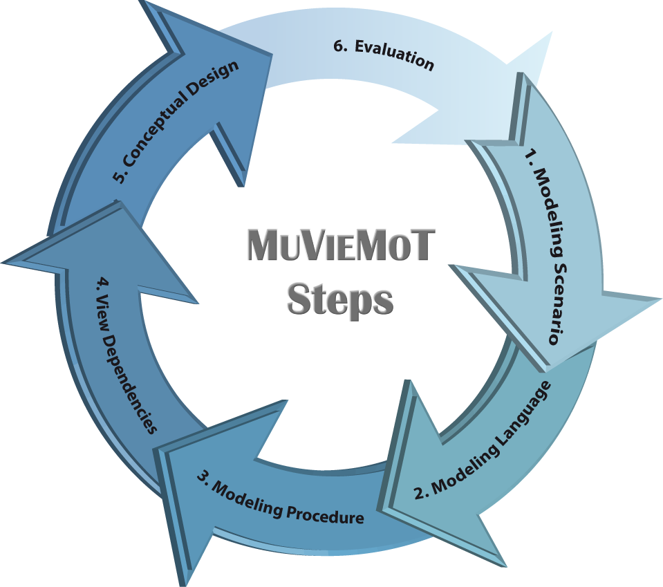
1. Modeling Scenario
The modelling scenario, specifies the situation in which a human modeler acts to create a model of an existing or postulated subarea of the real world. Thereby, the modeler is guided by the modeling method and supported by the modeling tool. The model of the realworld is decomposed into several viewpoints. Each viewpoint is defined by a relationship to one (i.e., projection) or more (i.e., selection) meta models and serves different goals, identified by stakeholders.
The goal of the first step is to define the global setting of a multi-view modeling method on an informal level. Within the modeling scenario, all information required during the succeeding steps is gathered.
2. Modeling Language
The second step of the lifecycle concentrates on the formalized specification of the meta models and the viewpoints of the modeling method. As an input, the informal specification of the modeling scenario is used and further refined. First, all meta models are modeled by referring to the concepts of modeling classes and relation classes. Cardinalities and inheritance relationships can be also defined. Subsequently, the modeling language for the viewpoints is defined by reusing the modeled classes of one or more meta models.
3. Modeling Procedure
Multi-view modeling methods come with specific requirements concerning the act of actually creating valid models. Therefore, an emphasis of the MuVieMoT approach is on the model-driven specification of the modeling procedure of a multi-view modeling method. This is realized by adopting conventional use case diagrams by adding the already specified viewpoints. All modeling actions, e.g., create, delete, modify an element, are connected with the viewpoints they can be triggered in. and those, the execution of a modeling action has an effect on. Consequently, in this step the defined viewpoints are reused and aligned with the functional requirements of a modeling tool (i.e., the modeling actions).
4. View Dependencies
Another vital characteristic of multi-view modeling tools is the consistency between the modeled views. The MuVieMoT tool traverses therefore traverses all modeled meta models and viewpoint models and visualizes the dependencies between the viewpoints. For each modeling element (i.e., modeling class and relation class) all viewpoints considering this element are visualized. The method engineer can further constrain the type of dependency, e.g. whether it is a complete 1:1 copy or if only some attributes needs to be kept consistent.
5. Conceptual Design
The conceptual design of the modeling tool specifies the tool from a functional perspective (model representation, modeling operations) as well as the user interface used for interaction with a human modeler. Additionally, non-functional requirements can be added in order to produce a comprehensive requirements specification model.
6. Evaluation
In the last step pf the MuVieMoT lifecycle, a solid evaluation of the conceptual design specification should be performed. First prototypical implementations of the specification can be given to the method owner in order to gain early feedback on the efficiency, completeness, and correctness of the modeling tool. The evaluation results might lead to another iteration of the MuVieMoT lifecycle.
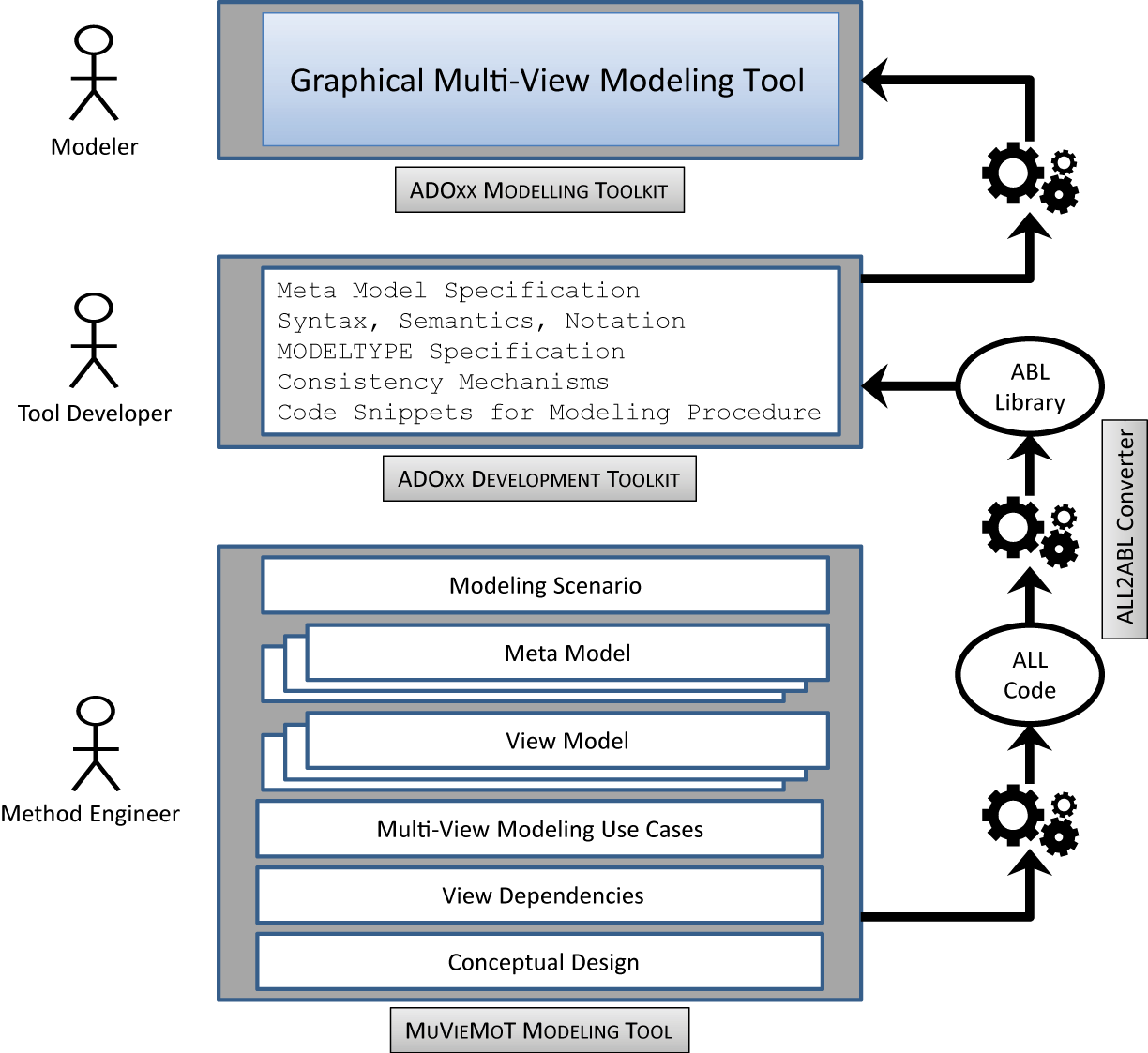
Roles and Tools in the MuVieMoT Lifecycle
The following figure illustrates comprehensively the roles and tools involved in the model-driven development of multi-view modeling tools with MuVieMoT. Ideally, three roles are distinguished: (1) A method engineer who uses the MuVieMoT tool to create a conceptual design, (2) a tool developer who uses this conceptual design and the initially generated multi-view modeling tool to implement the consistency-preserving mechanisms using the programming language of the platform, and (3) a modeler who uses the tool to create multi-view models.
Case Study
This page will introduce MuVieMot by providing a short case study. Following the stepwise approach suggested by the MuVieMoT lifecycle, the conceptual design of a multi-view modeling tool for the Semantic Object Model (SOM) method is defined. Afterwards, the transformation capabilities of MuVieMoT are used to initially derive a ADOxx modeling tool for SOM based on the created models.
A Multi-View Modeling Tool for the Semantic Object Model (SOM)
Foundations of SOM
The Semantic Object Model (SOM) is a comprehensive method for enterprise modelling with an emphasis on business process modelling and application systems specification. The first ideas of SOM have been published in 1990. The case study focusses on the business process modelling part of the SOM method.
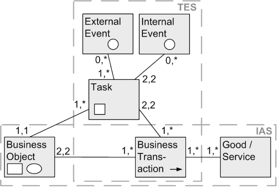
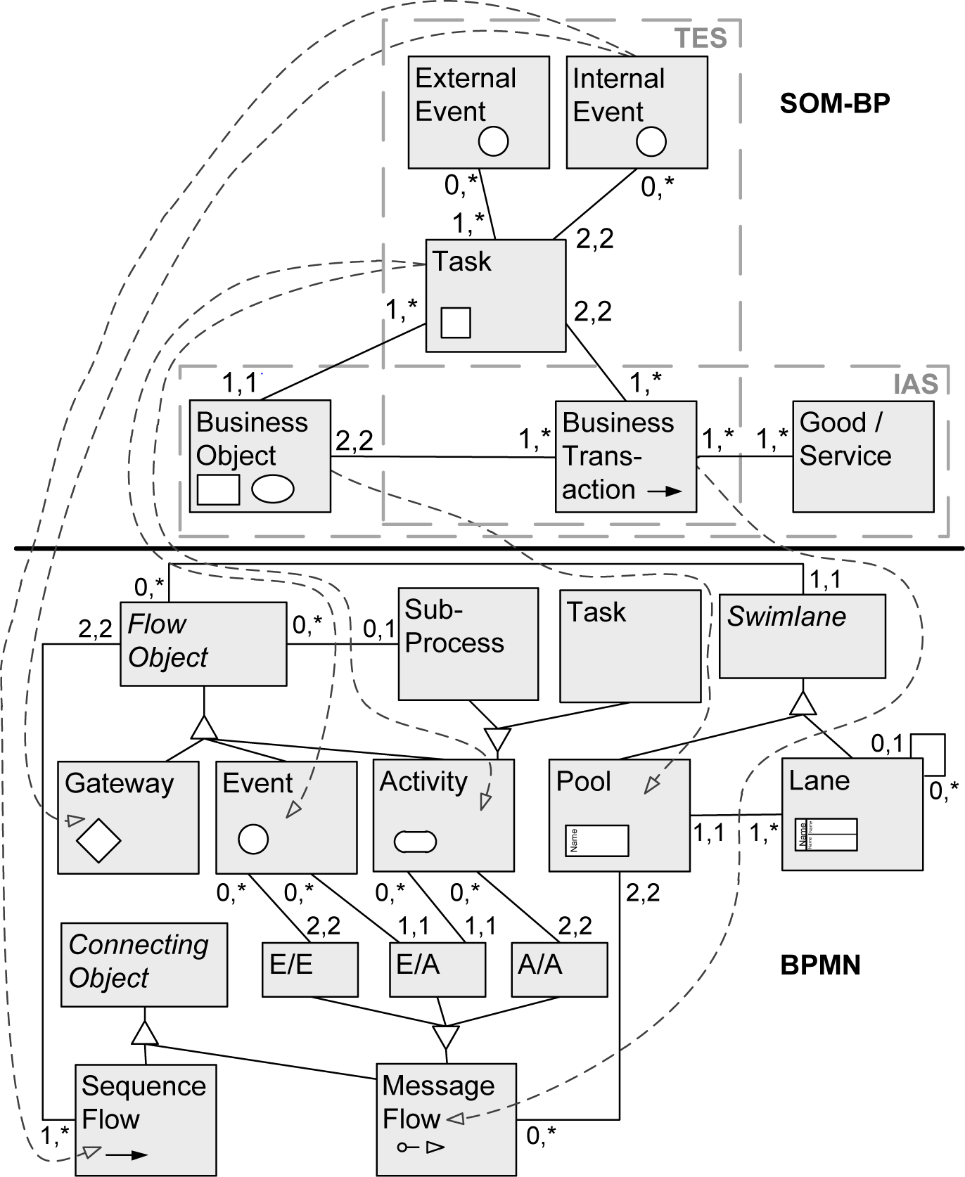
SOM business process modeling meta model
The centre of the meta-model for SOM business process models is built by the concepts of business object and business transaction. A business transaction coordinates two business objects. A business object can be involved in several business transactions. A business object comprises one or more business tasks, which are assumed to operate on the same object. A business transaction is performed by two tasks belonging to different business objects. Tasks belonging to the same object can be connected by an internal event. Moreover, the execution of a task can be triggered by an external event. Each transaction is involved in the coordination of at least one good or service.
SOM Viewpoints
SOM business process modeling follows a mulit-view modeling approach. For different viewpoints on a SOM bp model are defined: (1) a Interaction Schema (IAS), (2) a Task-Event Schema (TES), (3) a Object Decomposition Schema (ODS), and (4) a Trasnaction Decomposition Schema (TDS). The Interaction Schema visualizes a structural perspective on the bp by highlighting the business objects and their coordination using business transaction. The Task-Event Schema solely concnetrates on the behavioral perspective of the bp by adding a sequence of tasks, related to the business transactions. It thereby shows the execution of the business process. SOM bp modeling utilizes the recursive application of pre-defined decomposition rules to business objects and business transactions, respectively. Decomposition viewpoints therefore serve to provide a history of the decompositions performed by the modeler.
SOM Modeling Procedure
As mentioned earlier, creating business process modelis according to the SOM method does not utilize conventional drag & drop modeling. By contrast, the method defines concrete decomposition rules that must be applied to business objects and business transactions, respectively. By selecting the appropriate decomposition rule, the modeler reveals the coordination of the business objects in a hierachical or non-hierarchical manner.
Additionally to the complex decomposition rules, the SOM method also defines transformations of SOM bp models into models, specifying the business applications, realizing the processes. A SOM bp model can be transformed into a Schema of Task Classes (TAS), a Schema of Conceptual Classes (COS), and Business Process Modeling and Notation (BPMN) models.
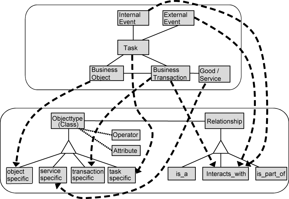
Mapping between SOM bp meta model and TAS/COS meta model
The illustration shows the transformation of SOM bp models into TAS and COS by providing a mapping between the concepts of the two meta models. This is enabled by the fact, that TAS and COS share a common meta model.
Mapping between SOM bp meta model and BPMN meta model
Realization with MuVieMoT
In the following, the realization of a conceptual desing for SOM business process modeling with the MuVieMoT modeling tool is discussed briefly. Following, the MuVieMoT lifecyle, for each step of the approach a model has been created. These task would normally be performed by the method owener of an already existing multi-view modeling method or by y method engineer who defines a new multi-view modeling method, respectively.
1. SOM Modeling Scenario
In the first step, a Modeling Scenario has been created. The MuVieMoT modeling tool supports the mehtod engineer with dedicated modeling concepts for this purpose. Using a Goal element, he or she can specify several goals using natural language. Goals can be aligned to stakeholders they are originating from or serving to. A metaphor can be defined, specifying the general way of carrying out modeling according to a multi-view modeling language (e.g., delimiting the subarea of the real world the modeling method is interested in etc..). The central elements of the Modeling Scenario model are the Meta Models and the Viewpoint Models. In the case of the SOM method, one integrted business process mdoeling meta model is specified by Ferstl and Sinz. All four Viewpoints (i.e., Interaction Schema, Task-Event Schema, Trasnaction Decomposition Schema, and Object Decomposition Schema) are defined by applying a projection operator to the integrated meta model.
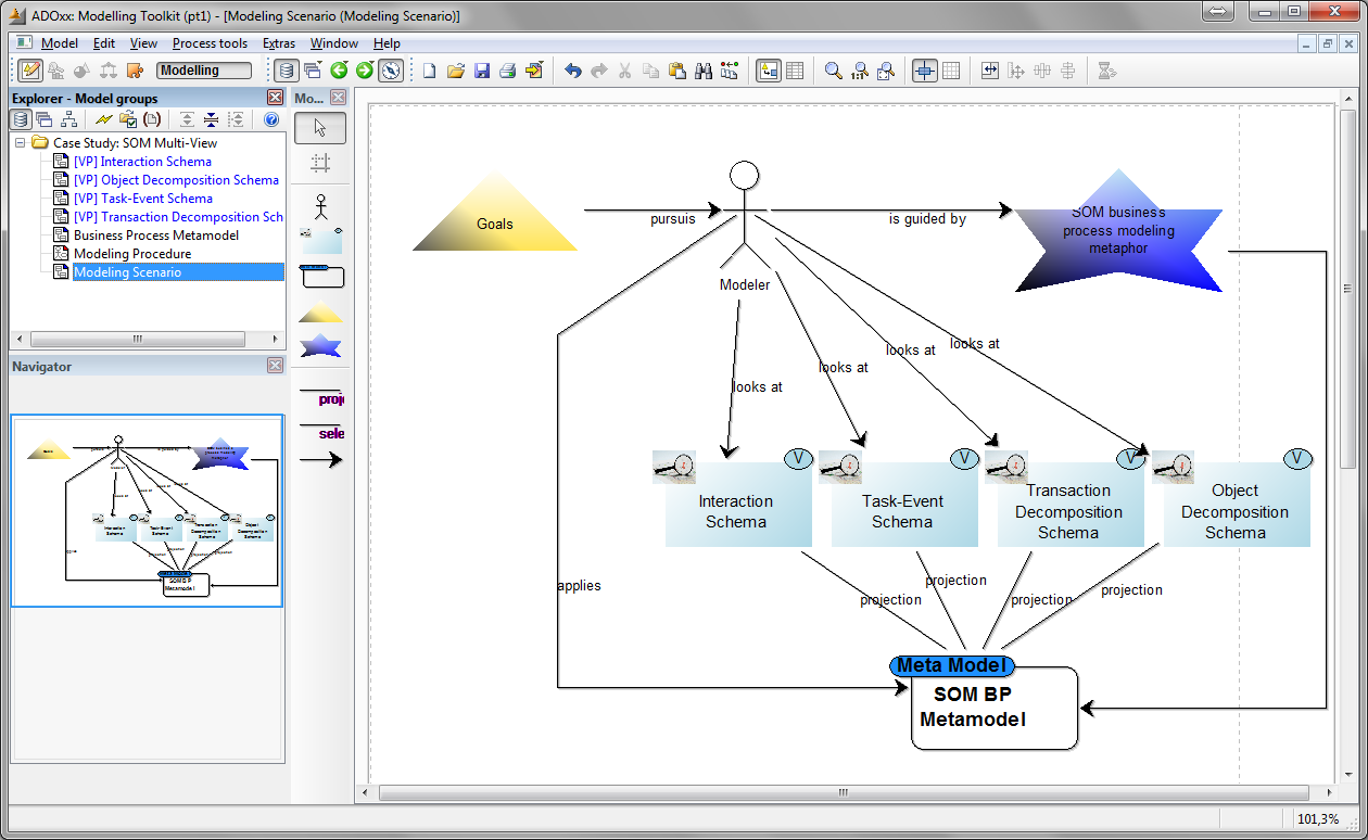
After everything is modeled and specified on an informal level, the method engineer can open the model attributes of the Modeling Scenario and select the 'Generate all Viewpoint models' functionality. A script is called that automatically generates a Viewpoint Model modeltype in ADOxx and names it according to the specification in the Modeling Scenario.
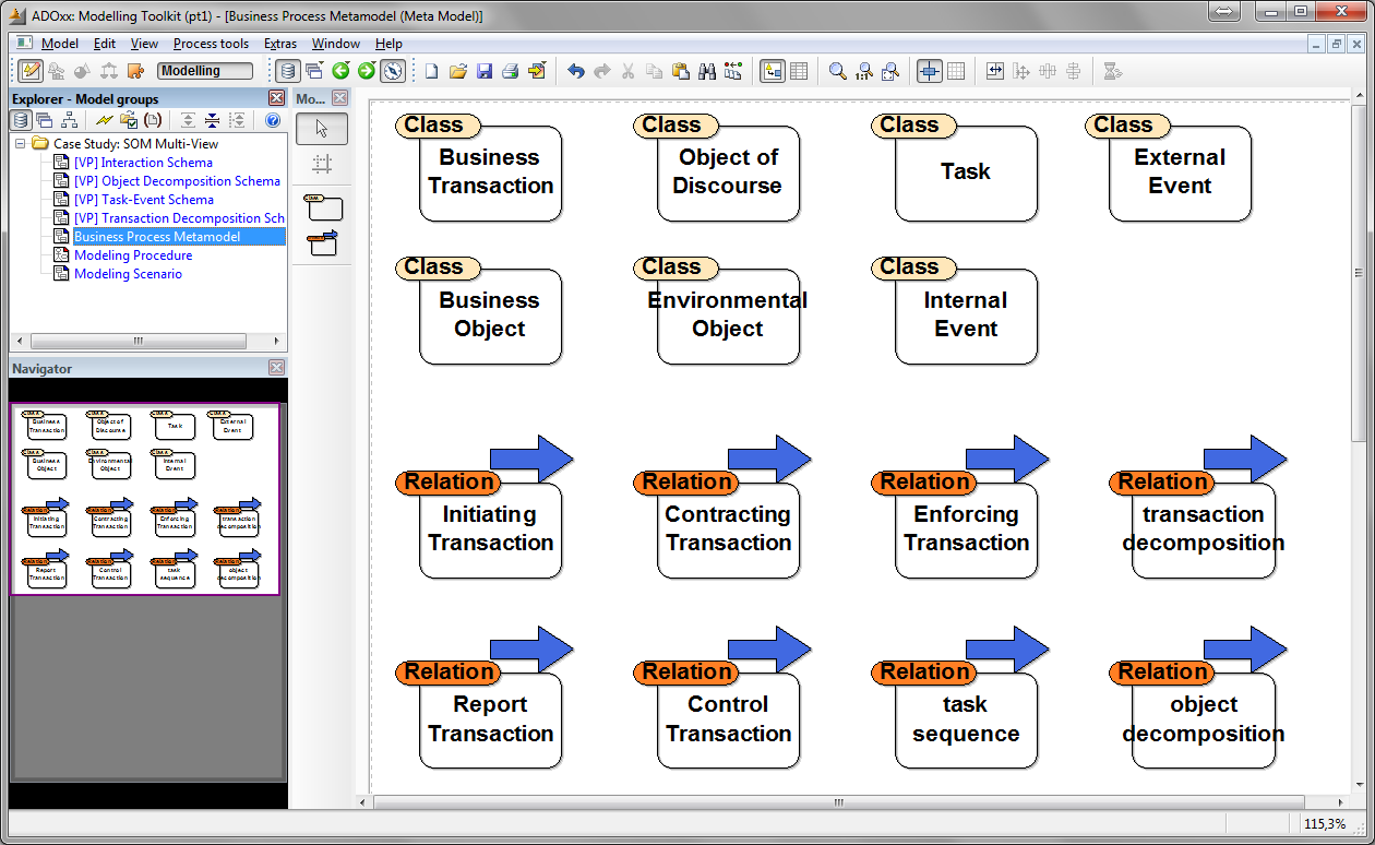
2. SOM Modeling Language
In the second step of the approach, the informally defined viewpoints and meta models need to be specified formally. The MuVieMoT tool has a specifically designed modeling language for the model-driven specification of meta models and viewpoint models. It utilizes the concepts 'Modeling Class' and 'Relation Class'. In the attributes of each Relation Class, the method engineer can specify between which Modeling Classes the Relation Class can be routed. Additionally, cardinalities can be defined, therefore further restricting the connectivity between the concepts. In the left figure, the complete meta model for SOM business process modeling is illustrated.
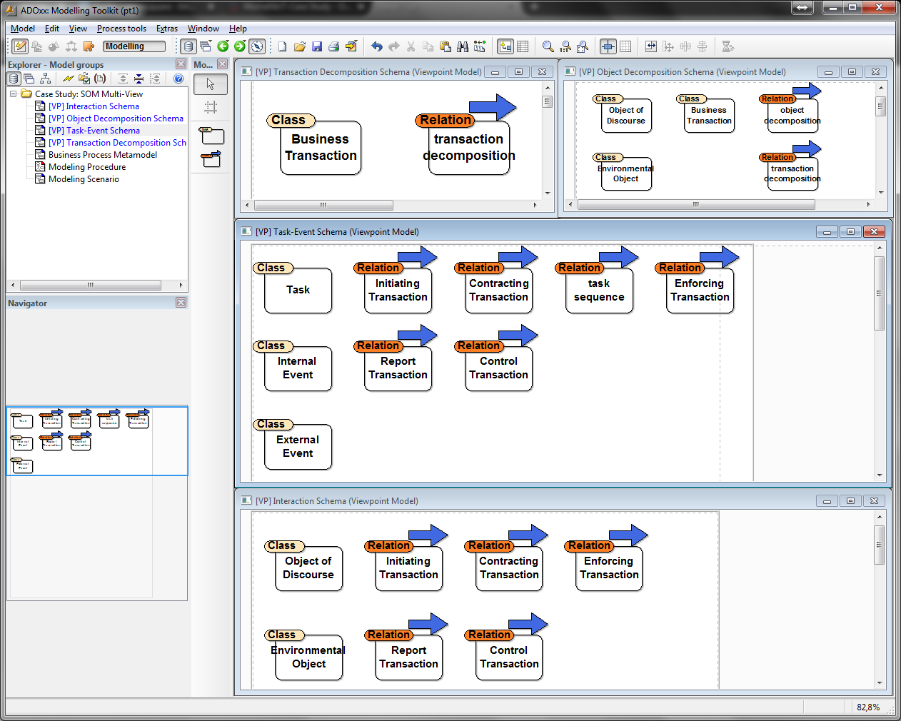
After the SOM business process meta model has been finished, the method engineer can copy & paste the elements considered in the respective Viewpoint models. Consequently, a Viewpoint only considers a certain subset of all concepts of the integrated meta model. The figure above on the right side shows the Viewpoint Model models of SOM created with the MuVieMoT tool.
3. SOM Modeling Procedure
The thir step specifies the application of the SOM multi-view modeling method, i.e., the actual creation of valid models by a modeler using the tool. The tools' functionality is specified by adopting conventional UML use case diagrams to the specifics of multi-view modeling methods. UML Actors are ignored as the actor is always the modeler. Instead, each use case is related to the Viewpoints it can be triggered in (visualized on the left border of the MuVieMoT tool) and the Viewpoints the execution of an use case has an effect on (vsualized on the right border of the MuVieMoT tool).
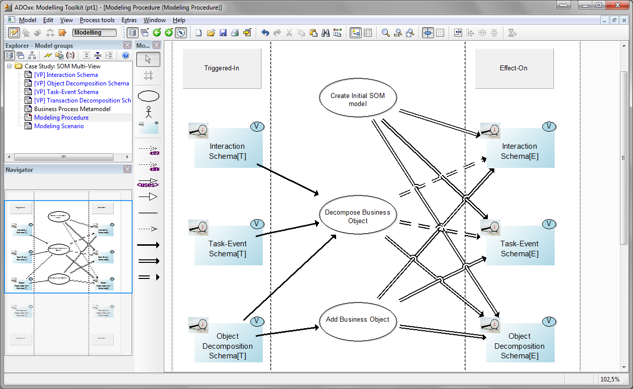
In the excerpt illustrated above, three use cases of SOM multi-view modeling are defined. For each use case can be defined, whether its execution has a direct effect on a certain Viewpoint, only a conditional effect, or not effct at all. Conditional effects are modeled using a dashed arrow whereas direct effects are modeled using a solid arrow. The conditions, determining the effect of an use case execution on a certain Viewpoint are then further specified in the Conceptual Design modeling step.
4. SOM View Dependencies
The MuVieMoT tool enables the automatic detection of syntactic dependencies between the multiple Viewpoints. Such dependencies are determined by an algorithm that traverses all Viewpoint Model and Metamodel Model models within the current modelgroup of the MuVieMoT tool. It searches for all Viewpoints and for all modeling concepts (i.e., Modeling Classes and Relation Classes) considered by them. The algorithm creates an inverted list with each modeling concept as a key and the list of Viewpoints considering that concept as value.
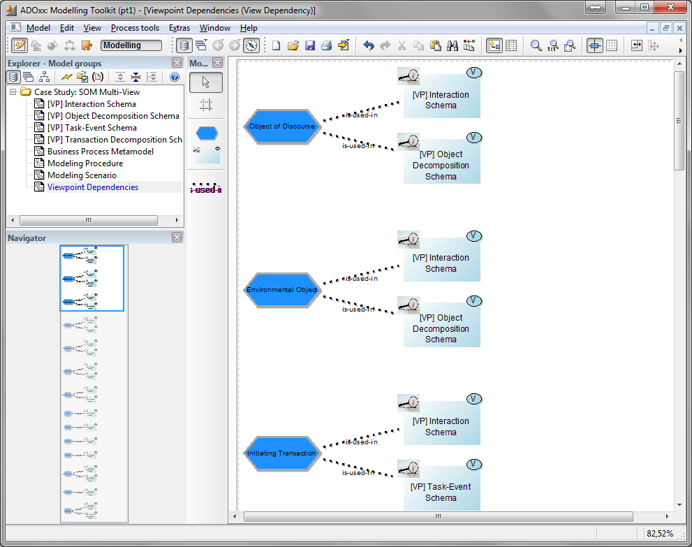
The figure shows the automatically generated visualization of this viewpoint dependency inverted list. Each modeling concept is illustrated on the left border and connected with the Viewpoints that include it. In the current version of MuVieMoT it is considered only a 1:1 relationship between the Viewpoints. Consequently, all Viewpoints have a copy of exact the same concept and all changes performed by the modeler (e.g., attribute value changes) are performed on all affected Viewpoints automatically in order to keep them consistent. In futur versions of the tool it should be possible to further constrain/specify the type of dependency between Viewpoints (e.g., only several attributes need to be kept consistent, concept a in Viewpoint one needs to be kept consistent with concept b in Viewpoint two, etc..).
5. SOM Conceptual Design
The last step uses all the information gathered in the preceding steps and condenses it into a comprehensive requirements specification for a multi-view modeling tool for the SOM method with an emphasis on consistency between the Viewpoints - in the following referred to as conceptual design. The Conceptual Design model of the MuVieMoT tool helps the method engineer by further specifying the functional and non-functional requirements of the SOM multi-view modeling tool.
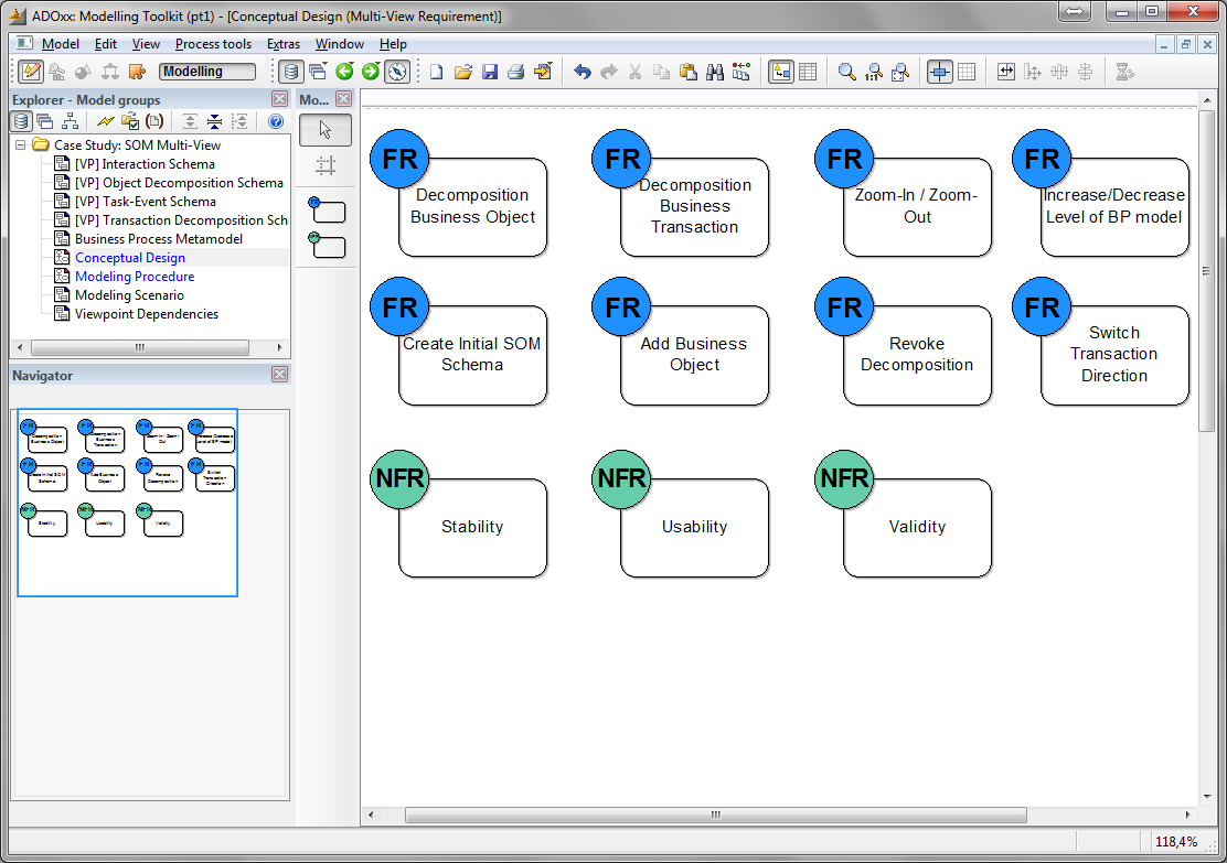
Using the Modeling Procedure model of step 3, the method engineer can use the use cases and transform them into functional requirements. Within the attributed (i.e., the ADOxx notebook) it is possible to comprehensively specify the effects and the consistency issues of a certain use case. This enables the tool developer to be more efficient and the resulting modeling tool to be strictly aligned to the specififc requirements of the SOM multi-view modeling method.
Model-Driven Development of the ADOxx Modeling Tool
The model-driven development of ADOxx multi-view modeling tools with MuVieMoTis pretty much straightforward. Four consecutive steps need to be performed:
Thid step requires the method engineer to create the Modeling Scenario and linking all defined meta models and viewpoints with respective Meta Model and Viewtype Model models in MuVieMoT.
Optionally, the method engineer can also create a Viewpoint Dependency model with ADOxx. With this model, he or she is able to autmatically detect syntacic dependencies inherently given by the meta models and viewpoint models. Moreover, semantic dependencies can be added manually. During the transformation process (Step 2) the method engineer is asked whether the dependencies should be included. MuVieMoT then automatically generates synchronization scripts that enbale automatic detection and correction of inconsistencies between the views in the Modeling Toolkit later on.
The method owner must open the Modeling Scenario model. Within this model the "Generate ALL Specification" functionality can be executed. After selecting the location where the "specification.all" file should be stored, an algorithm automatically traverses all models within the actual MuVieMoT project folder in ADOxx. The algorithm creates for each viewpoint model a ADOxx modeltype and adds all defined Modeling Classes and Relation Classes together with the defined attributes, e.g., for graphical visualization and the attribute visualization.
When the algorithm terminates, the ADOxx ALL2ABL webservice is called. Given the generated "specification.all" file, the webservice generates an ADOxx Application Lbrary file called "specification.abl" and stores it into the same local directory where the all-file is stored.
Next, the method engineer must launch the ADOxx Development Toolkit and import the "specification.abl" library file. After successful importation, a new user must be created and assigned to the library.
Finally, the ADOxx Modeling Toolit can be launched using the credentials of the new user. The new Modeling Toolkit enables multi-view modeling according to the specified modeling method.
The following screencast video shows the model-driven development of a SOM multi-view modeling tool following the MuVieMoT approach.
References
Please see the References section of the hompage for further details on the development of a SOM modeling tool with ADOxx (Bork and Sinz). First publications of the MuVieMoT approach and the corresponding modeling tool are currently uder review, they are added briefly after successful publication.
Further information on the SOM method can be found here:
Ferstl O.K., Sinz E.J.: Grundlagen der Wirtschaftsinformatik. 7. Auflage, Oldenbourg, München 2013
Ferstl O.K., Sinz E.J.: Modeling of Business Systems Using SOM. In: Bernus P., Mertins K., Schmidt G. (eds.): Handbook on Architectures of Information Systems. International Handbook on Information Systems, edited by P. Bernus, J. Blazewicz, G. Schmidt and M. Shaw, Volume I, 2nd Edition, Springer 2005
Tool
This page will shortly introduce the constituents of the MuVieMoT modeling tool. The architecture of the MuVieMot modeling tool is depicted in fig.1:
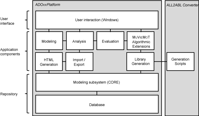
Figure 1: Architecture of the ADOxx implementation of MuVieMoT
A brief description of all modeltypes and their semantics/usage will be given. Moreover, the model-driven specification of multi-view modeling tools, using MuVieMoT, will be outlined.