In this area, a comprehensive case study showing the utilization of the SOM modelling tool is discussed. The case study is based on the publication of Ferst, Sinz, and Bork: Tool Support for the Semantic Object Model.
A product distribution process in SOM
In the following Section, the application of the SOM modeling tool is demonstrated by means of a case study, showing the different modeling steps to be applied in order to transform an initial SOM business process into a precise description of a distribution of goods/services between a distributor and a customer. SOM utilizes a top-down approach. Consequently, the case study starts by modelling SOM business process models. The created models are subsequently used for a model-driven generation of Schema of Conceptual Classes (COS), Schema of Task Classes (TAS), and Business Process Model and Notation (BPMN).
SOM business process modelling
To give an example, Fig. 1 introduces the business process distribution of a trading company visualized as a screen shot of the SOM modelling tool. At the initial level, the interaction schema view (bottom left modeltype) consists of three components, (1) the business object distributor which provides a service, (2) the transaction service which delivers the service to the customer (visualized in the transaction decomposition view on the upper right), and (3) the business object customer itself. Distributor is an internal object belonging to the universe of discourse while customer is an external object belonging to the environment. All business objects are visualized in the upper right view, the object decomposition view. At this level, the entire cooperation and coordination between the two business objects is specified by the transaction service.

Fig. 1: Initial SOM business process model
Fig. 1 (bottom right) shows the corresponding sequence of tasks which is very simple. The task names in the task-event schema are derived from the name of the corresponding transaction. Here, the task service > (say „send service“) of distributor produces and delivers the service, the task > service (say „receive service“) of customer receives it. The arrow service here defines the sequence of the two tasks belonging to the transaction service which is represented in the interaction schema by an arrow, too.
Transactions like service connect business objects inside the universe of discourse and link business objects to the environment. When modeling a value chain the business process model of a trading company includes a second business process procurement, which receives services from a business object supplier, belonging to the environment, and delivers services to a distributor.
The example (Fig. 1) will be continued now. For readability reasons, the figures concentrate on selected views in the following. The surrounding text will describe the modeling steps performed in all views. As customer and distributor negotiate about the delivery of a service, the service transaction is decomposed according to the negotiation principle into the sub-transactions i: price list (initiating), c: order (contracting), and e: service (enforcing transaction); visualized in the transaction decomposition schema in Fig. 2 a. The corresponding task-event schema (Fig. 2 d) is determined implicitly because the sub-transactions are executed in sequence. The tasks of each business object are connected by object-internal events.

Fig. 2: Transaction decomposition schema (a), object decomposition schema (b), interaction schema (c), and task-event schema (d) on the 2nd level
After this initial step, the resulting business transactions and business objects need to be further decomposed to more precisely depict the actual distribution of goods and services: First, the e: service transaction is decomposed into the sequence e:(seq.) delivery and e:(seq.) cash up. The cash up transaction is further decomposed according to the negotiation principle into the sequence c: invoice and e: payment (see Fig. 3 a). The initiating transaction is omitted because the business objects already know each other. The contract of the invoice transaction refers to amount and date of payment, not to the obligation to pay in principle which is part of the transaction c: order.
Second, the feedback control principle is applied two times to distributor to i) uncover the internal management of the business object, and ii) derive at a homogeneous mapping between business transactions and business objects. Following the feedback control principle, this leads to the sub-objects sales (management object), store (operational object), and finances (operational object). Sales and store are coordinated by the transactions r: delivery order (control transaction) and f: delivery report (feedback transaction). Sales and finances are coordinated by the transactions r: debit and f: payment report (see Fig. 3 b).

Fig. 3: Transaction decomposition schema (a) and object decomposition schema (b) on the 3rd level
Fig. 4 shows the interaction schema of the 3rd business process level. The sales sub-object deals with price list, (seq.) invoice and order, the store sub-object is responsible for delivery. Consequently, the finances sub-object takes care of the (seq.) payment.

Fig. 4: Interaction schema on the 3rd level
The last step in this case study is to define the behavior of the business process on its final decomposition level. Due to the different decomposition rules applied, the sequence of transactions cannot be derived automatically for the final process. Hence, the modeler is required to define the process behavior in the task-event schema by utilizing the internal event relationship and consecutively clicking on the outgoing and incoming task an internal event shall connect. Fig. 5 shows the final task event schema.
The business process is still initiated by the sales object sending a price list to the customer. The customer then sends an order back to sales. This initiates a control transaction delivery order to the store that actually delivers the good or service to the customer and responds with a feedback transaction (delivery report). After the report is processed, the sales object initiates two transactions: The sales object sends an invoice to the customer and it requests a debit to be handled by the finances. On receiving the customer’s payment the finances reports by means of a feedback transaction the payment report back to sales. This concludes the distribution process.

Fig. 5: Task-event schema on the 3rd decomposition level
Model-driven generation of a Schema of Conceptual Classes (COS)
The SOM tool enables the model-driven generation of Schema of Conceptual Classes (COS) models starting from a specific decomposition level depicted by a comprehensive SOM business process model. Fig. 6 illustrates the initial COS model derived from the final business process of the csae study. The transformation can be triggered within the tool's menu point Model Transformation => Generate Schema of Conceptual Classes (COS).
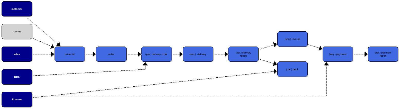
Fig. 6: Initially derived Schema of Conceptual Classes
After the transformation is terminated, the tool show a new model which includes all conceptual object types derived by the SOM business process model. The modeler may then revise this initial model by e.g., merging objecttypes, splitting an objecttype, introducing part-of relationships, geeneralization/normalization of objecttypes, or introducing completely new objecttypes. Fig. 7 shows a revised COS schemata. The objecttypes price list and order have been merged. The same procedure has been applied to payment and payment report due to the overlapping data and functionality of theses objecttypes. All functionality to revise initial COS schemata can be triggered within the context menu of objecttypes. Hence, in order to merge objecttypes, two or more objecttypes need to be selected and the corresponding Merge Objecttypes functionality needs to be triggered. Additionally, the tool also provides visualization functionality. Hence, the modeler can select to iterate over possible vertical orderings of the service specific objecttypes and object specific objecttypes on the left side of the model, e.g. in order to limit crossings between relationships. The Center COS functionality is also applied on Fig. 6 and 7, it realizes the transaction specific objecttypes to be positioned in a vertically centered manner.
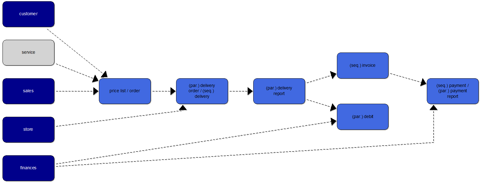
Fig. 7: A revised Schema of Conceptual Classes
Model-driven generation of a Schema of Task Classes (TAS)
The SOM tool enables the model-driven generation of Schema of Task Classes (TAS) models starting from a specific decomposition level depicted by a comprehensive SOM business process model. Fig. 8 illustrates the initial TAS model derived from the final business process of the csae study. The transformation can be triggered within the tool's menu point Model Transformation => Generate Schema of Task Classes (TAS). It is important to note, that the tool enables the modeler to select which classes to include during the transformation. Hence, the modeler may select single, several, or all objects in the starting business process model to be considered in the transformation. Fig. 8 illustrates the TAS which has been generated automatically based on the final business process model of the case study. Here, all objects have been selected.
Fig. 8: Initially derived Schema of Task Classes (TAS)
Model-driven generation of a Busienss Process Model and Notation (BPMN)
Following the research direction of Puetz and Sinz, SOM business process models can be transformed into initial Business Process Model and Notation (models). This enables the modeler to use the SOM business process on a higher abstraction level to generate initial workflow specifications based on BPMN. Fig. 9 shows an initially derived BPMN model based on the final business process model of the case study. The modeler has the possibility to further specify the BPMN using the context menu and/or the modeling palette on the left side.
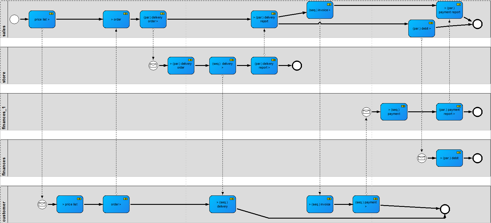
Fig. 9: Initially derived Business Proces Model and Notation (BPMN) model